RSM: A Key to Optimize Machining: Multi-Response Optimization of CNC Turning with Al-7020 Alloy
Summary
Excerpt
Table Of Contents
Contents
ACKNOWLEDGEMENTS
PREFACE
List of figures
List of Tables
CHAPTER 1
MACHINING AND CNC MACHINING
1.1 Machining: An Introduction
1.2 Machining Operations
1.2.1 Turning Operations
1.2.2 Tapered Turning
1.2.3 Hard Turning
1.2.4 Facing
1.2.5 Grooving
1.2.6 Boring
1.2.7 Drilling
1.2.8 Knurling
1.2.9 Reaming
1.2.10 Threading
1.3 An Overview of Machining Technology
1.4 CNC Lathe / CNC Turning Center
- Drills
- EDMs
- Embroidery machines
1.5 Present Work
1.6 Machining Parameters
1.6.1 Cutting Speed
1.6.2 Feed Rate
Formula to determine feed rate
1.6.3 Depth of Cut
1.7 Summary
CHAPTER 2
CUTTING TOOLS
2.1 Tools
2.2 Multiple Cutting-Edge Tools
2.3 Stages in Metal Cutting
2.4 Tool Material
2.5 Tool Wear
CHAPTER 3
ALUMINIUM AND ITS ALLOYS
3.1 Aluminium
3.2 Fundamentals of Aluminum Alloys
3.2.1 1XX.X Series Alloys
3.2.2 2XX.X Series Alloys
3.3.3 3XX.X Series Alloys
3.2.4 4XX.X Series Alloys
3.2.5 5XX.X Series Alloys
3.2.6 6XX.X Series Alloys
3.2.8 7XX.X Series Alloys
CHAPTER 4
RESPONSE SUFRFACE METHODOLOGY
4.1 RSM
4.1.1 Designs for First and Second-Degree Models
4.1.2 The 2k Factorial Design
4.1.3 The Plackett–Burman Design
4.4.4 The Simplex Design
4.2 Outline of ANOVA
4.3 Considered Responses
4.3.1 Material Removal Rate (MRR)
4.3.2 Surface Roughness (Ra)
4.4 Motivation of Study
CHAPTER 5 BACKGROUND OF MACHINING OPTIMIZATION
CHAPTER 6 MACHINING OF ALUMINIUM AND ITS ALLOYS
6.1 CNC Machining
6.2 Methodology Proposed
CHAPTER 7 MACHINING OPTIMIZATION: A CASE STUDY
7.1 Machining Parameters along with their Levels
7.2. RSM Matrix
7.3. Execution of Designed Experiments
7.4. RSM Statistics for MRR
7.5 Graphical Inferences for MRR
7.6 RSM Statistics for Ra
7.7 Inferences for Ra
7.8 RSM Solution
7.9. Validation of Solution through ANOVA
7.10 Relation In Between Responses
CHAPTER 8 CONCLUSIONS & SCOPE
8.1 Conclusion
8.2 Scope for Future
REFERENCES
WEB-SOURCES
List of figures
Figure 1 Turning
Figure 2 Taper Turning
Figure 3 Facing
Figure 4 External Grooving
Figure 5 Face Grooving
Figure 6 Boring
Figure 7 Drilling
Figure 8 Knurling
Figure 9 Threading
Figure 10 Lokesh TL 250 Used in Present Work
Figure 11 Geometry of a Single Point Turning Tool [[66]]
Figure 12 Multi Point Cutting Tool
Figure 13 Material Removal Rate
Figure 14 Surface Characteristics[[39]]
Figure 15 Surface Roughness Measuring Instrument
Figure 16 Data Normality Testing for MRR
Figure 17 Main Effect Plots for MRR
Figure 20 Surface Plot of MRR Vs Cutting Speed & Feed
Figure 21 Surface Plot of MRR Vs Depth & Feed
Figure 22 Data Normality Testing for Ra
Figure 23 Main Effect Plots for Ra
Figure 24 Two-Way Interaction Plot for Ra
Figure 25 Surface Plot of Ra Vs Feed & Cutting Speed
Figure 26 Surface Plot of Ra Vs Depth of Cut & Cutting Speed
Figure 27 Surface Plot of Ra Vs Depth of Cut & Feed
Figure 28 Predicted Responses
Figure 29Normal Probability Plot of MRR and Ra
Figure 30 Individual Value Plot of MRR and Ra at Machine Settings 1, 2 and 3
Figure 31 Box Plot of MRR and Ra at Machine Settings 1, 2 and 3
Figure 32 Pictures of Al-7020 (Samples) Turned at Different M/C Settings
Figure 33 Diagnostic Report of ANOVA for MRR and Ra at M/c Settings 1, 2 and 3
Figure 34 One way ANOVA Power Report for MRR at M/c Settings 1, 2 and 3
Figure 35 One way ANOVA Power Report for Ra at M/c Settings 1, 2 and 3
Figure 36 Process Capability w.r.t. MRR
Figure 37 Process Capability w.r.t. Ra
Figure 38 Correlations Between MRR and Ra
List of Tables
Table 1 Composition of Aluminium Alloy-7020
Table 2 Cutting Speeds for Various Materials Using HSS Cutter (Source: Wikipedia)
Table 3 Al Alloys
Table 4 Process Variables with Their Levels
Table 5 Orthogonal Matrix of RSM
Table 6 Execution of Experiments
Table 7 Statics for MRR
Table 8 ANOVA to Check RSM Statics
Table 9 Estimated Regression Coefficients for MRR
Table 10 Estimated Regression Coefficients for Ra
Table 11 ANOVA to Check RSM Statics (Ra)
Table 12 Estimated Regression Coefficients for Ra Using Data in Un-coded Units
Table 13 Response Optimization
Table 14 Responses on Machine Settings 1, 2 and 3
Table 15 One-way ANOVA for MRR (mm³/min) at M/c settings 1, 2 & 3
Table 16 One-way ANOVA for Ra (µm) at M/c Settings 1, 2 & 3
ACKNOWLEDGEMENTS
We would like to thank Er. Sirdeep Singh, Coordinator, PTU Regional Center, Bhai Gurdas Institute of Engineering and Technology, Sangrur, for his kind support.
We also owe our sincerest gratitude towards Prof. Rajbir Singh and Dr. S.S. Jolly for their valuable advice and healthy criticism throughout this work, which helped us immensely to complete this work successfully. We would like to thank the Dean Academics and members of the Departmental Research Committee for their valuable suggestions and healthy discussion during Commencement of the project work. We would also like to thank Prof. Manpreet Bains, Head, Department of Mechanical Engineering, Bhai Gurdas Institute of Engineering and Technology for his much needed support. We are deeply indebted to our parents whose motivation encouraged us in all times and finally made this publishing endeavor, possible. We would also like to thank everyone who has knowingly & unknowingly helped us throughout our work.
Last but not least, a word of thanks for the authors of all those books and papers which we have consulted during our present work as well as for preparing this book in present form.
Prof. Bikram Jit Singh
Prof. H.S. Sodhi
PREFACE
In present manufacturing scenario quality and quantity are two challenging aspects which are to be looked upon. Quality is important according to customer point of view, whereas quantity is required from the industrial point of view to maximize profit earnings. Both of these aspects are negatively co related with each other. For the sustainability of machining industry in today’s world there should be an optimized path which should be followed to satisfy both aspects.
This book gives rise to an optimization problem which should identify best combinations of various parametric variables. In a single objective optimization the output is only governed by a single parameter, whereas in multiple objective optimizations there are two or more conflicting variables which made further the optimization of responses, much difficult to achieve. The present study is done for optimization of turning parameters of a CNC turning center for Aluminium-7020 by using Response Surface Method (RSM). Tool used in the study is uncoated carbide tool ‘Taegutech TNMG 160408-GM-TT.3500’.
As the main response parameters considered here are Material Removal Rate (MRR) and Surface Finish (Ra) which mainly depends upon parameters such as Cutting Speed, Feed Rate and Depth of Cut. All these control parameters are directly or inversely related to each other. If the depth of cut is increased MRR increases at the same time we get poor surface finish. Increase in the cutting speed has positive impact on both material removal rate and surface finish. It employs that all the parameters are conflicting so we have to select the optimized parameters for the enhancement of the performance. Further the optimized results are verified by using ANOVA. This book indicates towards the practical feasibility of optimized turning in multi response conditions.
In chapter-1, an overview of machining technology has been provided. Introduction to Machining and its various common Machining Operations have been chalked out, suitably. Main focus is put on CNC machining With Lathe Turner. Light is put on machine actually being utilized during present case study along with its specifications. Various concerned process parameters (like; feed, dept of cut and cutting speed etc.) have been elaborated. At end of chapter rough plan of given book has been mentioned.
Chapter-2 highlights information about cutting tool by defining different tool geometry variables. It not only describes about stages included in metal cutting process but also signifies about the concept of tool wear in detail. Next chapter-3 emphasizes mainly on Aluminium and its alloys. It also demonstrates broad classification of Al alloys with its relevant applications. Chapter-4 discusses about Response Surface Methodology (RSM) in length. It shares the information about selected design of RSM in present case and elaborates Analysis of Variance (ANOVA) tool as a statistical tool being used during study, to further verify the achieved optimization of machining parameters. This also deals with the multiple responses (like; MRR and Ra) under consideration and talk about the need of present study in existing machining SMEs (especially in developing nations).
Chapter-5 represents the retrospective review of literature concerning Machining, CNC Machining, Non-Ferrous Machining and its respective Optimization, tried by different practitioners, engineers and machinists with time. Next chapter-6 describes the methodology adopted to optimize the present CNC machining through RSM for Al-7020 alloy. A comprehensive information regarding; CNC Machining of non ferrous alloy, RSM, actual experimentation performed and corresponding statistical analysis of RSM by ‘Minitab-16 Release’ software have been quoted, strategically in chapter-7. It also demonstrates the way to validate the achieved ‘Optimized Machine Settings’ with the help of ANOVA, appropriately. Conclusions have been made and future scope of such a work has been briefed in chapter-8. A complete list of references and web sources (as cited in book text) has been pasted at end of book for future consultation of readers.
CHAPTER 1
MACHINING AND CNC MACHINING
1.1 Machining: An Introduction
Machining is a process in which a piece of raw material is cut into a desired final shape and size through a controlled material-removal activity. Traditional machining processes consist of turning, boring, drilling, milling, broaching, sawing, shaping, planning, reaming and tapping. In these "traditional" or "conventional" machining processes, machine tools like; lathes, milling machines, drill presses, or others, are used with a cutting tool to remove material and achieve a desired geometry (Oberg. 2004). The new technologies include; electrical discharge machining (EDM), electrochemical machining (ECM), electron beam machining (EBM), photochemical machining and ultrasonic machining etc. In current usage, the term "machining" usually implies the traditional machining processes that may be performed on conventional or CNC machines.
Machining is used to manufacture many metal products and further can also be used on materials such as wood, plastic, ceramic and composites. A person well versed in machining is known as a machinist. A room, building or company where machining is executed is called a machine shop. Much of modern day machining is performed out through computer numerical control (CNC), in which computers are used to monitor and control the movement or operation of the mills, lathes and other cutting machines.
1.2 Machining Operations
The major three principal machining processes are classified as turning, drilling and milling. Other operations falling into miscellaneous category include; shaping, planning, boring, broaching and sawing (Groover, 2007). Turning operations are one that rotates the work piece against the cutting tool. Lathes are the principal machine- tool used in turning. Turning is a machining process in which a cutting tool, typically a non-rotary tool bit, describes a helical tool path by moving linearly while the work piece rotates. The tool's axes of movement may be literally a straight line or they may be along some set of curves or angles, but they are essentially linear (in the non-mathematical sense). Usually the term "turning" is reserved for the generation of external surfaces by cutting action, whereas this same essential cutting action when applied to internal surfaces (that is, holes, of one kind or another) is known as "boring". Thus the phrase "turning and boring" categorizes the larger family of (essentially similar) operations. The cutting of faces on the work piece (that is, surfaces perpendicular to its rotating axis), whether with a turning or boring tool, named as "facing", and may be lumped into either category as a subset.
Turning can be performed manually, in a traditional form by lathe, which frequently requires continuous supervision by the operator or by using an automated lathe, which does not. Today the most common type of such automation is computer numerical control, better known as CNC. (CNC is usually used with many other types of machining besides turning). When turning a piece of relatively rigid material (such as wood, metal, plastic or stone) is rotated and a cutting tool is traversed along axes of motion to produce precise diameters and depths. Lathes could even be used to manufacture complex geometric figures but since the advent of CNC it has become unusual to use non-computerized tool path control for this purpose.
The turning operations are typically carried out on a lathe, considered to be the oldest machine tools and can be of four different types such as straight turning, taper turning, profiling or external grooving. Those types of turning processes can produce different shapes of materials such as straight, conical, curved or grooved work piece etc. In general, turning utilizes simple single-point cutting tools. Each group of work piece materials has an optimum set of tools angles which have been developed through the years. The bits of waste metal from turning operations are called ‘chips’ (in North America) or ‘swarf’ (in Britain). In some areas they may be called just ‘turnings’.
1.2.1 Turning Operations
This operation is one of the most basic machining operations. That is, the part is rotated while a single point cutting tool is moved parallel to the axis of rotation (Todd, 1994). Turning (refer figure 1) can be done on the external surface of the part as well as internally (boring). The starting material is generally a work piece generated by other processes such as casting, forging, extrusion, or drawing (Google, 2013). Straight turning may he performed upon a work piece supported in a chuck, but the majority of work pieces turned on an engine lathe are turned between centers. Turning is the removal of metal from the external surface of cylindrical work pieces using various types of cutter tool bits.
Abbildung in dieser Leseprobe nicht enthalten
Figure 1 Turning
(Source: Google Images)
1.2.2 Tapered Turning
In straight turning, the cutting tool moves along a line parallel to the axis of the work, causing the finished job to be the same diameter throughout. However during taper cutting the tool moves at an angle to the axis of the work, producing a taper (Yahoo, 2013). Therefore, to turn a taper, the work must either be mounted on a lathe so that the axis upon which it turns is at an angle to the axis of the machine, or cause the cutting tool to move at an angle to the axis of the machine (see figure 2).
Abbildung in dieser Leseprobe nicht enthalten
Figure 2 Taper Turning
(Source: Yahoo Images)
Taper turning can be performed from following ways:
- By the compound slide
- By taper turning attachment
- By Using a hydraulic copy attachment
- Using a C.N.C. lathe
- Using a form tool
- By the offsetting of the tailstock - this method is more suitable for shallow tapers.
1.2.3 Hard Turning
Hard turning is a turning operation done on materials with a Rockwell Hardness greater than 45. It is typically performed after the work piece is heat treated. The process is intended to replace or limit traditional grinding operations. It is applied for purely stock removal purposes and competes favorably with rough grinding. However, when it is used for finishing where form and dimension are critical then grinding is superior. Grinding produces more dimensional accuracy of roundness and cylindricity. In addition, polished surface finishes of Rz 0.3-0.8z cannot be achieved with hard turning alone. Hard turning is appropriate for parts requiring roundness accuracy of 0.5-12 micrometers, and/or surface roughness of Rz 0.8–7.0 micrometers. It is used for gears, injection pump components, hydraulic components and among other applications.
1.2.4 Facing
Facing is a type of turning work, which involves moving the cutting tool at right angles to the axis of rotation of the rotating work piece (Koepfer, 2010).
Abbildung in dieser Leseprobe nicht enthalten
Figure 3 Facing
(Source: Wikipedia)
This can be performed by the operation of the cross-slide, if one is fitted, as distinct from the longitudinal feed (Wikipedia, 2013). It is frequently the first operation performed in the production of the work piece and often the last one also (look at figure 3 for details).
1.2.5 Grooving
According to Wikipedia Grooving is like parting, except that grooves are cut to a specific depth instead of severing a completed/part-complete component from the stock (Wikipedia, 2013). Grooving can be done on internal and external surfaces, as well as on the face of the work piece. (Also known as face grooving or trepanning, refer figure 4 and 5).
Abbildung in dieser Leseprobe nicht enthalten
Figure 4 External Grooving
(Source: Wikipedia)
Abbildung in dieser Leseprobe nicht enthalten
Figure 5 Face Grooving
(Source: Wikipedia)
Grooving is like parting, except that grooves are cut to a specific depth instead of severing a completed/part-complete component from the stock. Grooving can not only be executed on internal and external surfaces but it can also be on the face of the part (face grooving or trepanning). Other Miscellaneous machining operations are described briefly as under:
1.2.6 Boring
Enlarging or smoothing a hole created by drilling or moulding etc. The machining of internal cylindrical forms (generating) can be possible either by mounting work piece to the spindle via a chuck and faceplate or by mounting work piece onto the cross slide and placing cutting tool into the chuck (see figure 8 for more description).
Abbildung in dieser Leseprobe nicht enthalten
Figure 6 Boring
(Source: Ask.com Images)
On long bed lathes large work pieces can be bolted to a jig or fixture (on the bed) and a shaft is made to pass between two lugs of the work piece. Further these lugs can be bored out to size (Wikipedia, 2013).
1.2.7 Drilling
Drilling is a process of making a hole of required diameter in the work piece. Drilling process is of great significance from manufacturing point of view (Bralla, 1999). Drilling process is highlighted in the figure 6 as below.
Abbildung in dieser Leseprobe nicht enthalten
Figure 7 Drilling
(Source: Google Images)
Drilling is used to remove material from the inside of a work piece. This process uses standard drill bits held stationary in the tail stock or tool turret of the lathe (Google, 2013). The process can be executed by separately available drilling machines.
1.2.8 Knurling
Knurling is a process of creating diamond like cuts on the surface of the part which assists in its proper gripping. Knurling process is done with a specific knurling tool as described in figure 7 ahead.
Abbildung in dieser Leseprobe nicht enthalten
Figure 8 Knurling
(Source: Yahoo Images)
The cutting of a serrated pattern onto the surface of a part (for a better hand grip) through application of a special purpose ‘knurling tool’ is known as Knurling Operation (Yahoo Search, 2013).
1.2.9 Reaming
The sizing operation that eliminates a small amount of metal or material from an existing hole is called Reaming. It is done for making internal holes of very accurate diameters. For example, a 6mm hole is made by drilling with 5.98 mm drill bit and then reamed to achieve accurate dimensions (Ask.com, 2013).
1.2.10 Threading
Both standard and non-standard screw threads can be turned on a lathe by using an appropriate cutting tool. (Usually having a 60° or 55° nose angle) Either externally or within a bore generally referred to as single-point threading (look at figure 9).
Abbildung in dieser Leseprobe nicht enthalten
Figure 9 Threading
(Source: Bing Images)
Tapping of threaded nuts and holes can be done through hand taps or by using a tapping device with a slipping clutch to reduce risk of breakage of the tap (Bing, 2013). Threading operations include all types of external and internal thread forms using a single point tool also taper threads, double start threads, multi start threads, and worms as used in worm wheel reduction boxes, lead screw with single or multi-start threads. By the use of threading boxes fitted with 4 form tools, up to 2" diameter threads but it is possible to find larger boxes than this.
1.3 An Overview of Machining Technology
Machining is any process in which a cutting tool is used to remove material in the form of small chips from the work piece (the work piece is often called the "part"). To perform the operation, relative motion is required between the tool and the part. This relative motion is achieved in most machining operation by means of a primary motion, called "cutting speed" and a secondary motion called "feed". The shape of the tool and its penetration into the work surface, combined with these motions, produce the desired shape of the resulting work piece.
1.4 CNC Lathe / CNC Turning Center
Numerical control (NC) machine is an automated machine-tool that is operated by precisely programmed commands encoded on a storage medium (in contrast with manually controlled via; hand wheels, levers or cams alone). Most of NC machines are today computer numerical controlled (CNC), in which computers play an integral part of the control (Smid, 2008). The first NC machines were built in 1940s and 1950s, based on existing tools that were modified with motors that moved the controls to follow points fed into the system on punched tape. These early servomechanisms were rapidly augmented with analog and digital computers, creating the modern CNC machine tools that have revolutionized the machining processes, afterwards.
CNC Machine Variants
Computer numerical controlled (CNC) lathes are rapidly replacing the older production lathes (multi-spindle, etc.) due to their ease of setting, operation, repeatability and accuracy. These are designed to use modern carbide tooling and are more compatible with modern technology. The part may be designed and the tool paths are programmed by the CAD/CAM process (or manually by the programmer) and the resulting file is uploaded to the machine. After setting and taking trials, the machine will continue to turn out parts under the occasional supervision of an operator. Following are some of the few areas where CNC is working successfully:
- Drills
- EDMs
- Embroidery machines
- Lathes
- Milling machines
- Wood routers
- Sheet metal works (Turret punch)
- Wire bending machines
- Hot-wire foam cutters
- Plasma cutters
- Water jet cutters
- Laser cutting
- Oxy-fuel
- Surface grinders
- Cylindrical grinders
- 3D Printing
- Induction hardening machines
- submerged welding
- knife cutting
- glass cutting
The machine is controlled electronically via a computer menu style interface. The program may be modified and displayed at the machine, along with a simulated view of the process. The setter/operator needs a high level of skill to perform the process, however the knowledge base is broader compared to the older production machines where intimate knowledge of each machine was considered essential. These machines are often set and operated by the same person, where the operator will supervise a number of machines (or cells).
The design of a CNC lathe varies with different manufacturers, but they all have some common elements (Herrin, 1998). The turret holds the tool holders and can be indexed as per need, the spindle holds the work piece and there are slides that let the turret move in multiple axis simultaneously. The machines are often totally enclosed, due in large part to occupational health and safety (OH&S) issues. With rapid growth in this industry, different CNC lathe manufacturers use different user interfaces which sometimes make it difficult for operators as they have to be acquainted with them (Zhou et al., 1995). With the advent of cheap computers, free operating systems such as: Linux and open source CNC software, the entire price of CNC machines has been slashed. In modern CNC systems, end-to-end component design is highly automated using computer-aided design (CAD) and computer-aided manufacturing (CAM) programs. The programs produce a computer file that is interpreted to extract the commands needed to operate a particular machine via a post processor and then loaded into the CNC machines for production (Wannas, 2008). Since any particular component might require the use of a number of different tools – drills, saws, etc., modern machines often combine multiple tools into a single "cell". In other installations, a number of different machines are used with an external controller and human or robotic operators that move the component from machine to machine (Taj and Morosan, 2011). In either case, the series of steps needed to produce any part is highly automated and produces a part that closely matches the original CAD design.
Nowadays, more and more Computer Numerical Controlled (CNC) machines are being used in every kind of manufacturing processes (Suresh et al., 2002). In a CNC machine, functions like: program storage, tool offset and tool compensation, program-editing capability, various degrees of computation and ability to send and receive data from a variety of sources, including remote locations can be easily realized through on board computer (Boubekri et al., 2010). The computer can store multiple-part programs, recalling them as needed for different parts (Sahoo et al., 2008).
1.5 Present Work
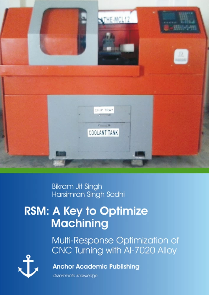
In present case, the machine in focus is ‘Lokesh TL 250’ a CNC lathe having Siemen’s control system with the spindle speed ranges from 500 rpm to 4000 rpm, feed rate up to 20 mm/rev and 16 KVA power rating (refer figure 10). For generating the turning surfaces, CNC part programming for tool paths are created with specific commands (Mahdavinejad and Sharifi, 2009).
Abbildung in dieser Leseprobe nicht enthalten
Figure 10 Lokesh TL 250 Used in Present Work
(Source: Ashoka Gears Patiala)
Tool Used: Commercially available carbide tool Taegutech TNMG 160408 –GM – TT.3500 with nose radius 0.8 mm is used in the present investigation. Compressed Sam Soil coolant is used as cutting environment.
Material Used: The present study is carried out with Al 7020 aluminium alloy. The chemical composition of aluminium alloy is enlisted in the table below. Al-Zn alloys 7020 have the following composition by weight percentage (see table 1).
Abbildung in dieser Leseprobe nicht enthalten
Table 1 Composition of Aluminium Alloy-7020
1.6 Machining Parameters
The effects of following turning parameters have been taken into account to optimize the machining responses like: Material Removal Rate (MRR) and Surface Finish (Ra).
1.6.1 Cutting Speed
Cutting speed may be defined as the rate (or speed) that the material moves past the cutting edge of the tool, irrespective of the machining operation used. In other words, it is the speed at which the metal is removed by the tool from the work piece (Google, 2013). In a lathe it is the peripheral speed of the part past the cutting tool expressed in meters per minute For a given material, there will be an optimum cutting speed for a certain set of machining conditions and from this speed the machine’s spindle speed (RPM) can be calculated. Factors affecting the calculation of cutting speed are:
- The material being machined (steel, brass, tool steel, plastic, wood) (see table below).
- The material of the cutter (Carbon steel, high speed steel (HSS), carbide and ceramics).
- The economical life of the cutter (the cost to regrind or purchase new as compared to the quantity of parts produced) Cutting speeds are calculated on the assumption that optimum cutting conditions exist, these include (Wikipedia, 2013):
- Metal removal rate (finishing cuts that remove a small amount of material may be run at increased speeds).
- Full and constant flow of cutting fluid (adequate cooling and chip flushing).
- Rigidity of the machine and tooling setup (reduction in vibration or chatter).
- Continuity of cut (as compared to an interrupted cut, such as machining square section material in a lathe).
- Condition of material (mill-scale, hard-spots due to white cast iron forming in castings etc.)
The cutting speed is given as a set of constants that are available from the material manufacturer (or supplier). The most common materials are available in reference books or charts but will always be subject to adjustment depending on the cutting conditions. The table 2 gives the cutting speeds for a selection of common materials under one set of conditions. The conditions are a tool life of 1 hour, dry cutting (no coolant) and at medium feeds so these may be appeared to be incorrect depending on circumstances.
Abbildung in dieser Leseprobe nicht enthalten
Table 2 Cutting Speeds for Various Materials Using HSS Cutter (Source: Wikipedia)
These cutting speeds may change if, for instance, adequate coolant is available or an improved grade of HSS is used (such as one that includes cobalt). The spindle speed is the rotational frequency of the spindle of the machine, measured in revolutions per minute (rpm). The preferred speed is determined by working backward from the desired surface speed (sfm or m/min) and incorporating the diameter (of work piece or cutter). The spindle may hold the:
- Material (as in a screw machine)
- Drill bit in a drill
- Milling cutter in a milling machine
- Router bit in a wood router
- Shaper cutter or knife in a wood shaper or spindle moulder
- Grinding wheel on a grinding machine.
- Or it may hold the chuck, which then holds the work piece in a lathe. In these cases the tool is often a stationary tool bit, although there are plenty of exceptions, such as in thread milling.
[...]
Details
- Pages
- Type of Edition
- Erstausgabe
- Publication Year
- 2014
- ISBN (Softcover)
- 9783954892099
- ISBN (PDF)
- 9783954897094
- File size
- 14.9 MB
- Language
- English
- Publication date
- 2014 (February)
- Keywords
- Response Surface Methodology Non-Ferrous Machining CNC Machines Material Removal Rate Surface Roughness
- Product Safety
- Anchor Academic Publishing
